CALL 702-848-3990
0
Shopping Cart
Products
Dust Collector Filters & Cages
Baghouse Filters
PTFE Filters & Membrane
Pleated Filters
Cartridge Filters
Dust Collector Filter Cages
Filter Hardware
Pleated Dust Collector Filter Conversion: Cost-Benefit Analysis
Industrial Dust Collection Systems
Cartridge Collectors
Baghouse Collectors
Cyclone Collectors
Bin Vents
Oil Mist Collectors
What Kind Of Dust Collector Is Right For Me?
Combustible Dust Accessories
Fire Suppression
Explosion Vents
Baghouse Spark Arrestors
Baghouse Accessories
Solenoid Valves
Pressure Gauges
Air Locks
Pulse Valves
Tensioning Tools
Door Gasket Seals
Sonic Horns
Leak Testing Products
Precoat Powder
Dust Collector Control Boards
HEPA Filter
Conveying Systems
IoT Tools
Sensors & Monitoring
Schedule a Free DustIQ Readiness Assessment
Services
System Design Calculators
Air-to-Cloth Ratio Calculator
Interstitial Velocity Calculator
Can Velocity Calculator
Total Filter Cloth Area Calculator
Leak Testing Powder Calculator
Precoating Powder Calculator
Air Velocity Calculator
Duct Size Calculator
Our Training Programs
In-Person Maintenance Training & Inspection
Online Training
Log In
Enroll
Virtual Training
Combined Training
How To Enroll
Watch Our Webinars
Filter Replacement
Dust Collection System Audits
Southern California – Dust Collection System Audits
Houston, Texas – Dust Collection System Site Visits
Las Vegas, Nevada – Dust Collection System Site Visits
Dustvent Parts and Service
Dust Hazard Analysis (DHA)
Contact Us
System Quote
Service Quote
Filter Quote
Accessories & Hardware Quote
About Us
The Baghouse.com Advantage
Spend Less On Baghouse Operation
Industries Served
Metalworking and Foundries
Woodworking
Mining and Quarrying
Food Processing
Agriculture
Chemical and Pharmaceutical Manufacturing
Cement and Construction Materials
Energy Production
Automotive and Aerospace Manufacturing
Plastics and Rubber Processing
FAQs
Dust Collection Blog
Case Studies
Case Study – Turning Challenges into Solutions at a Wood Shop
Case Study – Innovative Solutions for Cosmetics Manufacturing
Case Study — Expansion at Sunshine Minting
Case Study — Turning Challenges into Solutions at a Woodshop
Case Study — Dust Collection Optimization in Asphalt Production
Case Study — Dust Collection Optimization in Gypsum Manufacturing
Case Study — Dust Collection Enhancement in Chemical Manufacturing at Teknor Apex
Case Study — Dust Collection System Upgrade for Gibson Guitars
Case Study — Combustible Dust Safety in Aerospace Manufacturing
Case Study — Operational Improvements at Blue Diamond Growers
Case Study — Dust Collection in the Mining Industry
Dust Collection 101
Baghouse Accessories
Baghouse Design
Dust Collector Maintenance
Dust Collector Troubleshooting
Industrial Health and Safety Regulations
Purchasing Supplies Tips
Dust Collection News
Log In
EN
ES
Search
Menu
Menu
Facebook
LinkedIn
Youtube
X
Mail
Dust Collection Blog
Latest Articles
Categories
Dust Collection 101
Baghouse Accessories
Baghouse Design
Dust Collector Maintenance
Dust Collector Troubleshooting
Industrial Health and Safety Regulations
Purchasing Supplies Tips
Dust Collection News
Frequently Asked Questions
Dust Collection 101
Baghouse Accessories
Baghouse Design
Dust Collector Maintenance
Dust Collector Troubleshooting
Industrial Health and Safety Regulations
Purchasing Supplies Tips
Dust Collection News
Frequently Asked Questions
The Complete Guide to Dust Collection Hood Design
Baghouse Accessories
,
Baghouse Design
,
Dust Collection 101
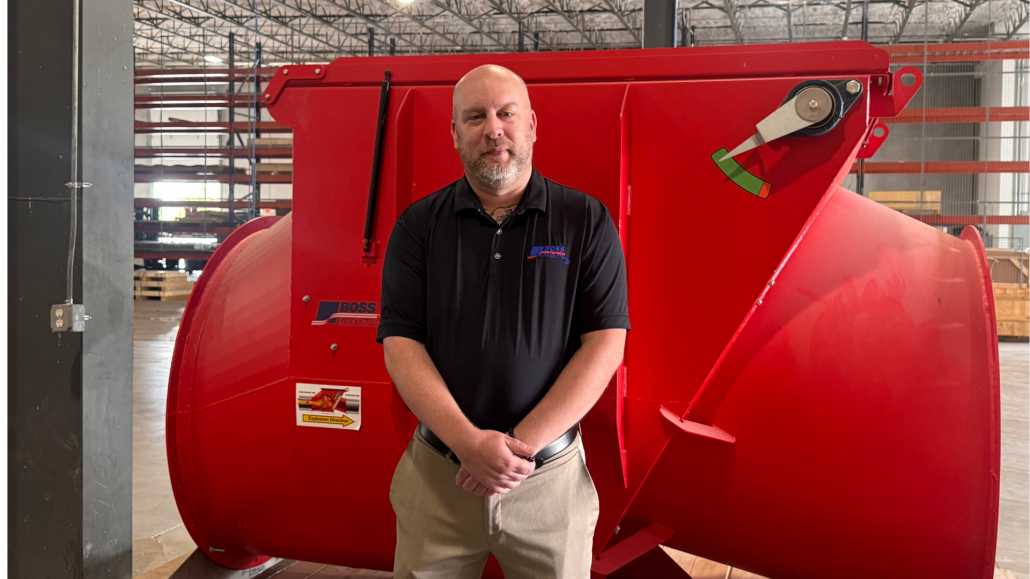
Interview With Joe Kastigar from Boss Products — Common Combustible Dust Challenges
Baghouse Accessories
,
Baghouse Design
,
Industrial Health and Safety
,
Safety
Dust Collection Explained: A New Video Training Series
Baghouse Design
,
Baghouse FAQs
,
Dust Collection 101
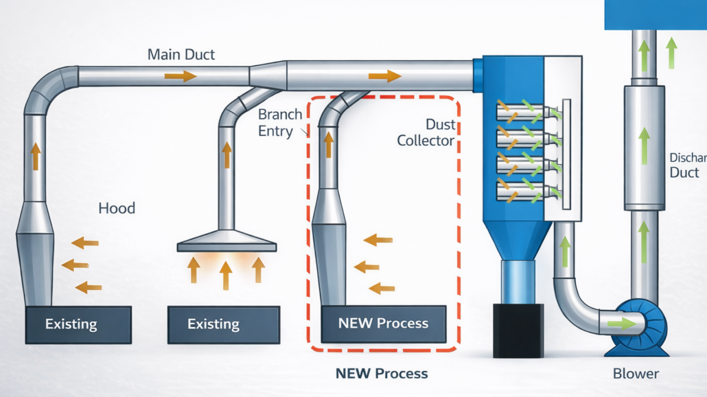
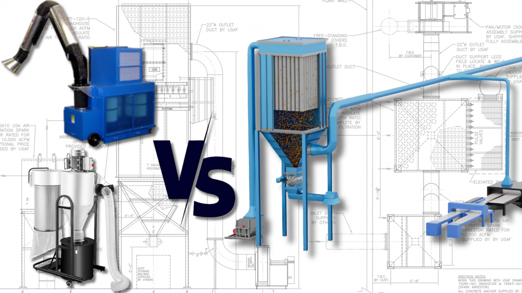
Should I Use a Portable Dust Collector or a Central Dust Collection System?
Baghouse Design
,
Baghouse FAQs
,
Dust Collection 101
What Are the Direct and Indirect Costs Associated with Your Dust Collection System?
Baghouse Design
,
Baghouse FAQs
,
Dust Collection 101
NEW FREE WEBINAR: Improving Dust Collection in Cement Plants and Mining
Baghouse Design
,
Mining and Quarrying
Case Study — How We Designed a Dust Collection System for 1440 Foods’ Powder Mixing Expansion
Baghouse Design
,
Case Study
,
Food Processing
,
Industrial Health and Safety
Case Study — Dust Collection and Bulk Storage for Ribus Seed Processing Operations
Agriculture
,
Baghouse Design
,
Case Study
,
Food Processing
Case Study — Designing a Large-Scale Dust Collection System for Wonderful Foods
Agriculture
,
Baghouse Design
,
Case Study
,
Food Processing
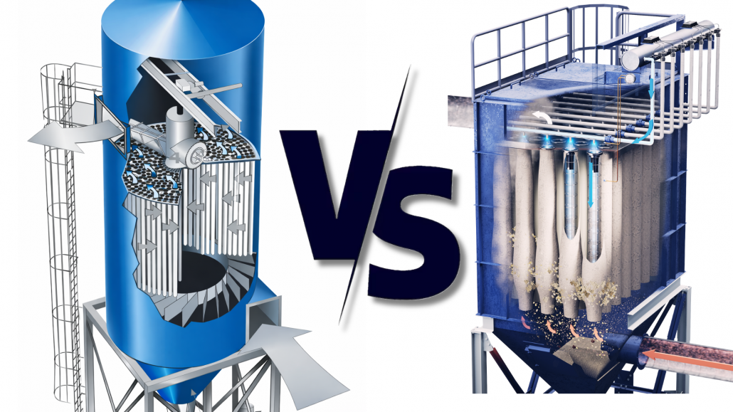
What is the Difference Between Medium Low-Pressure Reverse Air and Pulse-Jet Baghouses?
Baghouse Design
,
Dust Collection 101
Page
1
Page
2
Page
3
Page
4
Get a quote today!
CONTACT US
Scroll to top