We continue from our last article where we reviewed the 4 key design variables of airflow (in CFM), static pressure/resistance, air velocity and air to cloth ratio. Now we can begin calculating these variables for our new dust collection system. When we are finished we will know exactly how large of a baghouse we will need (including how much filter area required) along with our fan output (x airflow @ y static pressure).
The sizing and design process can be divided into two stages. The first stage involves sizing your duct work for adequate volume (CFM) and velocity (ft/m) for the type of dust you will be handling. Then in the second phase you calculate the static pressure (SP) of your system to determine the size of your baghouse (how many filters and what size) and power of your system fan. If you already have a ductwork system and want simply to replace an existing baghouse/fan combo, you still need to calculate the CFM and static resistance from the existing ductwork system to properly size the baghouse and/or fan.
Step 1 – Find the Minimum Conveying Velocity (ft/m) of Your Product
Determine from a reputable source the minimum conveying velocity for the material the system will handle. The box on the right lists several common materials and their recommend conveying velocities. Most materials require between 3,500 ft/m to 5,000 ft/m. A more extensive list can be found on Baghouse.com
Step 2 – Identify Total Number of Primary and Secondary Sources
Sizing your system requires you to determine how many much airflow you need at each location. Begin by making a list of all the equipment you plan to vent with the dust collection system. Identify your primary and secondary sources that you will connect to the system.
Primary Sources need constant venting whenever system is running. Some facilities may have only one large source to vent (e.g. a single boiler, furnace, etc.). Others may have many different systems but each one requires its own system as the different equipment cannot be connected for some reason (e.g. gypsum plants, cement plants, process applications)
Secondary Sources do not always run concurrently without primary sources and sometimes shutdown completely. Secondary sources are common in wood/metal milling, fabrication and manufacturing shops. For example, a woodworking shop uses several different pieces of equipment such as saws, lathes and sanders requiring dust collection. While the large saw and lathe run continuously everyday (primary), a small specialty-use sander and a planner are only used once or twice a week (secondary) and never at the same time as each other. In this example, you would size your system to handle the two primary sources (saw and lathe) and only one of the two secondary sources (sander and planer) as they will never run at the same time. Plan with the objective of defining the heaviest use scenario so you can size your system to meet it. Incorporating pickup points that see limited or infrequent use may result in an oversized the system, which increases its total cost to purchase, operate and maintain. Plan wisely, as increasing capacity post installation is nearly impossible. A good rule of thumb is to oversize the system by roughly 10% to ensure proper operation and accommodate any future expansions.
Primary or Secondary Source?
- Take care to correctly classify each piece of equipment
- Classifying all sources as primary sources will result in an unnecessarily large system, increasing initial installation costs and making it more costly to operate in the long run.
- Classifying too many sources as secondary sources will result in an undersized system, resulting in insufficient capacity for normal operations. This will produce production bottlenecks or inadequate venting leading to health/safety hazards.[/box]
Step 3 – Calculate Total CFM Required for Each Branch
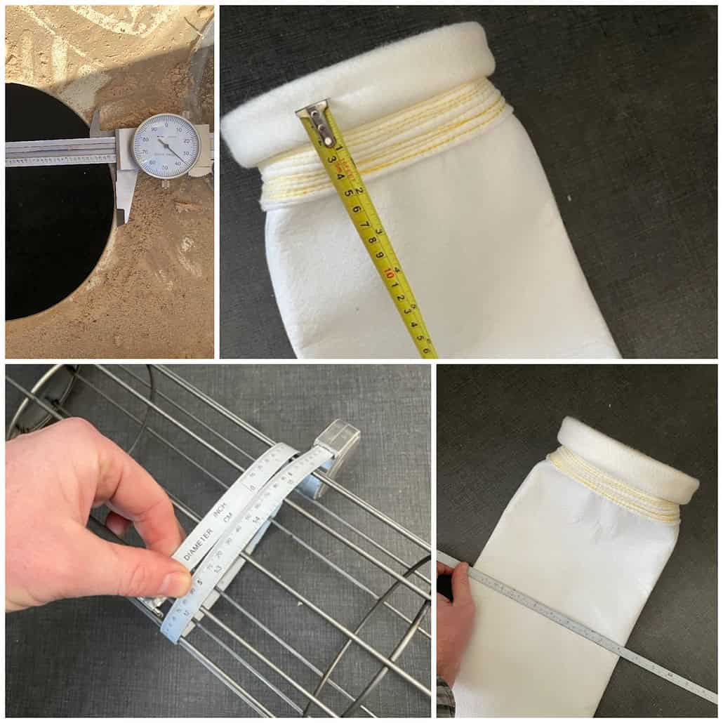
In the next step, determine how much CFM you need at each branch of your system. If your source equipment has a built in collar or port identify the diameter (if rectangular calculate the total cross sectional of the duct and convert to round equivalent). On larger sources such as kilns, furnaces or process equipment or for sources with custom-designed venting determine CFM required by consulting with the equipment OEM or by using industry-best practice methods. (Consult a dust collection expert experienced in the specific application for advice.) Finally, using the chart in this section find your duct size and match to column with the required conveying velocity to find the needed CFM for each branch.
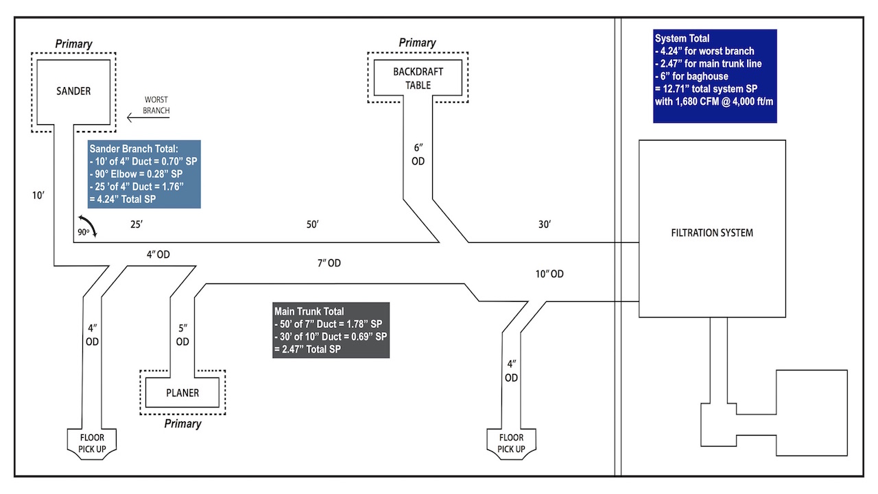
Determining CFM for Each Branch in Our Example System – To illustrate we have prepared a sample system layout for consideration of this design step (See illustration below. We will continue to use this same example throughout the following 3 sections.)
Here we have a woodworking shop with a total of (5) pickup points. We have a sander, backdraft table, planer and two floor pickups. Next we determine the CFM required for each branch by duct diameter and then matching it to the appropriate conveying velocity required for wood (see chart in previous section)
- (1) Sander = 4” OD @ 4,000 ft/m = 350 CFM (rounded)
- (1)Planer = 5” OD @ 4,000 ft/m = 550 CFM (rounded)
- (1)Backdraft table = 6” OD @ 4,000 ft/m = 780 CFM (rounded)
- (2) Floor pickups = 4” OD @ 4,500 ft/m = 400 CFM (For reference only, secondary sources are not counted towards final total.)
Baghouse.com Expert Tips Many types of equipment come with built-in connections for dust collection. These ports are sized by the manufacturer to provide sufficient ventilation while operating the equipment. Simply confirm the diameter of the port to calculate the required CFM (using chart in this section) for the unit.
Step 4 – Create a System Layout and Size Your Main Trunk
Now we need to create a layout of the ductwork system, deciding where it will connect to each machine and where we will place the dust collector. This will determine what size ducts we need including our main trunk line. To help illustrate these concepts we will continue to refer to our sample system first described in the previous section.
Steps to Layout Your System and Size Your Main Trunk
- Make rough floor plan showing the location of each piece of equipment
- Sketch layout of ductwork connecting each piece of equipment together and running all the way back to the dust collector
- Where two primary branches meet combine the CFM require by each branch (using figures from previous step) and calculate the duct size needed to provide sufficient CFM for both branches at the required air velocity (where needed round up to next largest duct size)

Make Floor Plan of Equipment – Take your primary and secondary sources and make a rough floor plan of every piece of equipment. Once you have every source in its approximate location map out the ductwork connection each piece back to the collector. Try to locate your dust collector in a central, convenient location. Safety regulations covering applications involving combustible dusts (e.g. wood, metals, grains, etc.) may mandate placing the baghouse outside or on an exterior wall (along with explosion venting to the outside).
Create Rough Layout of Ductwork System – Now each piece of equipment needs to be connected together and run back to the baghouse. Start at the source farthest away from your collector. Using the CFM requirements you calculated for each branch in the previous step, note the diameter of the duct required and map it out running towards the collector to the point where the next branch connects. Additionally, note the length of each run of duct (important for next step).
Where the next branch connects add the CFM of both lines together and determine what size duct you need for that amount of CFM at the required velocity in ft/m. Increase the size of the duct accordingly and continue mapping the trunk forward. Repeat the process and increase the duct size only at each spot where a primary source connects to the main trunk. Continuing mapping your main trunk (making sure to connect to all primary and secondary sources) until you reach the collector.
Sample shop layout – Notice our calculations for the required CFM, air velocity and the total static resistance generated by the system. Now you can determine the required filter area (i.e. number of filters in the collector) and the fan power.
Determining Duct Size for Each Branch and Main Trunk in Our Example System – First, we begin with the farthest source the sander. Its built in connection port is 4”, so we begin with a 4” duct leading out of it. Then we continue running it where it connects with the 5” duct coming from the planer. (NOTE We do not increase the size where it meets the Floor Pickup, as this is a secondary source.) By combining 4” duct requiring 350 CFM and the 5” duct requiring 550 CFM, we get 900 CFM +/- at 4,000 ft/m (see previous section for more details). Where these two combine we need a duct to handle at least 900 CFM@ 4,000 ft/m. According to our chart, this falls between a 6” and 7” duct. Per best practice, we will move up and oversize the duct slightly to ensure sufficient airflow and allow for possible expansion later.
Continuing on the 7” duct next combines with the 6” duct running from the backdraft table. The 6” duct requires 780 CFM +/- and the 7” duct requires 1068 CFM. Again, the total combined CFM falls in between the 9” and 10” OD duct, so we size up to 10”. Finally, with all the primary sources connected, the system requires at least 1,680 CFM @ 4,000 ft/m.
Now we have sufficient CFM for all of our primary branches. We also have a safe amount of oversizing to ensure adequate operation and provide a cushion for any possible future expansion. To accommodate the other secondary branches we can install blast gates on all the branches and close off other lines.
Baghouse.com Expert Tips:
- Try to keep the largest equipment closest to where you will place your dust collector.
- Try to run your ductwork in the shortest possible route.
- Always size up if the required CFM falls between two duct sizes. This allows for future expansion.
- Only increase the duct size when a primary source branch connects, but do not forget to run trunk so that all the secondary sources can connect as well.
- Consult fire/safety regulations may require the dust collector be located on an external wall or outside.[/box]
Step 5 – Calculate The Static Pressure (i.e. Static Resistance) of Your System
Static pressure or static resistance (measured in inches of water w.g.) refers to the amount of resistance to airflow created friction and channeling of air through the ductwork. For the system to work the system fan must overcome the resistance created by the ductwork and the baghouse. Accurately calculating the static pressure or SP of the system is crucial for the system to function correctly. To determine the total SP of your system you must add the SP generated by following three elements together:
- The branch with the great SP (also known as the Worst Branch)
- The SP of the main trunk line, including any fire protection/prevention devices
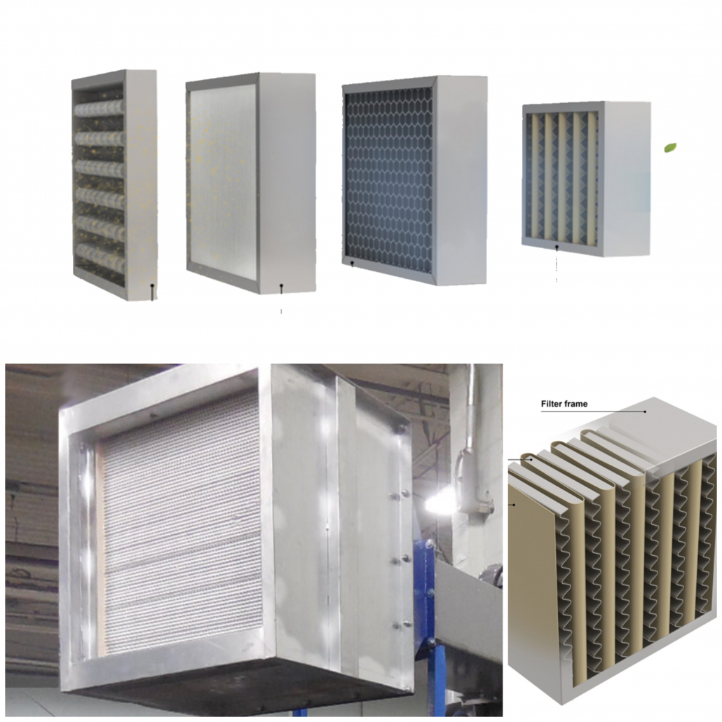
- The resistance created by the dust collector(s). This would include any precleaners (cyclones, knockout chambers, etc.) as well as the filters within the baghouse.
Calculate the SP of all your branches and identify the one with the greatest amount of resistance in w.g. (Likely the branch farthest from the unit with have the highest SP, but not always.) Only figure the SP of the worse branch into your calculations for the entire system’s SP. Next, move on to the main trunk line. Calculate the resistance created by the duct diameter and the length of each section, along with any elbows, splits, or other connections. Finally, identify the SP generated by the dust collector(s), which in most cases will be only a baghouse. For most baghouses plan on a maximum of 5”-7” of resistance (most baghouses should run between 3”-5” differential pressure, but sizing slightly above this figure is conservative and allows for some flexibility).
Steps to Calculate System Static Pressure (i.e. Static Resistance)
- Identify the branch with the highest static pressure (Worst Branch)
- Calculate the SP of the main trunk line
- Determine SP of dust collector
Determining Static Pressure for Each Branch, Main Trunk and The Baghouse in Our Example System
Step 1 – Find the Branch with the Highest SP – Starting at each piece of equipment work back through to the main trunk and determine the total SP of each branch. In our example, the sander branch has the great resistance.
- Entry loss at equipment adaptor of 1.5” (constant)
- 10’ of 4”OD duct
- Reference Table 2-3 shows 100’ of 4” OD duct @ 4,000 ft/m = 7.03”
- 10’ = 7.03 x .1 (for 10’ feet out of 100’) = 0.70” SP
- (1) 90° elbow
- Reference Table 2-4 shows (1) 90° elbow of 4” OD is equivalent of 6’ of straight pipe
- 6’ of 4 OD = 0.28” SP
- 25’ of 4” OD duct
- Reference Table 2-3 shows 100’ of 4” OD duct @ 4,000 ft/m = 7.03”
- 25’ = 7.03 x .25 (for 25’ feet out of 100’) = 1.76” SP
- 1.5” + 0.70” + 0.28” + 1.76” = 4.24” Total SP for sander branch
Step 2 – Calculate SP of Main Trunk Line – In our example our ductwork has 50’ of 7” OD duct, followed by 30’ of 10” OD duct at 4,000 ft/m.
- 50’ of 7” OD duct
- Reference Table 2-3 shows 100’ of 7” OD duct @ 4,000 ft/m = 3.55”
- 50’ = 3.55 x .5 (for 50’ feet out of 100’) = 1.78” SP
- 30’ of 10” OD duct
- Reference Table 2-3 shows 100’ of 10” OD duct @ 4,000 ft/m = 2.30”
- 30’ = 2.30 x .3 (for 30’ feet out of 100’) = 0.69” SP
- 1.78” + 0.69” = 2.47” SP Total SP for main trunk line
Step 3 – Calculate SP for Dust Collector – Each type of dust collectors generates different SP. For this figure, it is best to consult with an experienced baghouse OEM such as Baghouse.com. For our example we will assume a SP of 6” for a baghouse dust collector. Note: Baghouses are normally designed to operate between 3” – 5” of differential pressure. Baghouse.com recommends being conservative with this estimate and designing in extra capacity to provide a cushion for normal operational ups and downs.
- 6” Total SP for baghouse
Total SP for our example system:
- 4.24” for worst branch
- 2.47” for main trunk line
- 6” for baghouse
- = 12.71” total system SP
Now we have all the data needed for completing our system. The dust collection system must provide a minimum airflow of 1,680 CFM through a 10” trunk duct at air velocity 4,000 ft/m with a static pressure of at least 12.71” w.g.
[/et_pb_text][et_pb_text admin_label=”Text” global_module=”3337″ saved_tabs=”all” background_layout=”light” text_orientation=”left” use_border_color=”off” border_color=”#ffffff” border_style=”solid”]
Next Section – Part 4 – Additional Considerations for Dust Collection System Design