For a dust collection system to function adequately engineers must design and operate the system to maintain the (4) key design parameters of airflow (measured in CFM), airflow velocity (measured in FPM), Static Pressure/Static Resistance and Air to Cloth Ratio (or A/C). Changes to any of these key system parameters will result in systemwide performance issues. All four of these parameters are fluid and directly affect the others. Maintaining all at proper levels requires careful engineering, operation and maintenance. Lets review these four parameters one by one.
Airflow in CFM (Cubic Feet per Minute)
CFM – What Is it? – How much air the system moves is measured in Cubic Feet per Minute or CFM. (Related terms include ACFM for Actual Cubic Feet per Minute and SCFM for Standard Cubic Feet per Minute). Most often baghouses are sized and categorized according to CFM. In general, the larger the space being vented or the greater the number of pickup points in the system the more CFM required. The CFM generated by the system fan can be fixed or adjusted (Variable Frequency Drive or VFD Fans). However, total CFM generated by a fan can be affected changes in altitude, ductwork restrictions and sizing as well as resistance to flow created by the system (ductwork + filters).
Why Important? – Without sufficient CFM the sources will not be vented adequately. Poor venting directly causes damage to equipment, high emissions, loss of reclaimed product and hazardous environment (especially of concern in facilities handling combustible dusts or hazardous materials). Low CFM can also negatively affect air velocity, air to cloth ratio, and vacuum pressure, other key design parameters.
Vacuum Pressure (Suction) & Static Pressure (Static Resistance)
What Are Static Pressure and Static Resistance? – Vacuum pressure or suction is measured in inches of water gauge, w.g. and is the basis of a properly functioning dust collection system. The system fan must supply enough suction to pull the materials from the collection point(s) all the way through the ductwork to the baghouse and then through the filters and out to exhaust. To do that it must overcome the resistance to flow created by the filters and the ductwork. Conversely, static pressure or static resistance is a measurement of resistance generated by the ductwork and the filters in baghouse. This also is measured in inches of water gauge.
Why Important? – Without sufficient CFM the sources will not be vented adequately. Poor venting directly causes damage to equipment, high emissions, loss of reclaimed product and hazardous environment (especially of concern in facilities handling combustible dusts or hazardous materials). Low CFM can also negatively affect air velocity, air to cloth ratio, and vacuum pressure, other key design parameters.
Air Velocity and Minimum Conveying Velocity
What are Air Velocity and Minimum Conveying Velocity? – Air velocity within the system is measured in feet per minute, or ft/m. The system must be carefully engineered to keep the air speed within an acceptable range to prevent two major issues. Air speed is related to CFM as follows: ft/m = CFM ÷ cross sectional of duct (i.e. size of duct).

Dust builds up within the ductwork when the air velocity is too low causing blockages and affecting airflow and performance.
Why Important? – High air velocity can quickly wear holes the ductwork by means of abrasion (especially abrasive dusts like metals, ceramics, etc.) or can break up delicate conveyed products such as processed foods (cereals), pharmaceuticals, and others. Of greater concern is low air velocity, which can cause dust buildup within the ductwork and lead to poor dust capture at inlets. For a dust to travel suspended in air it must most at or above the minimum conveying velocity for that product. If it drops below that minimum speed at any point in the ductwork the dust will begin to settle or dropout of the airstream, which then accumulate into large piles that eventually choke off the duct. These accumulations of dust within the ductwork create major safety hazards. When combined with an ignition source (such as a spark or ember) they provide ample fuel for a combustible dust fire or explosion, which then can propagate throughout the entire system, being continually fed by dust accumulations further downstream until it reaches the dust collector. Additionally, these accumulations can eventually become so large that the duct collapses under the added weight.
Air to Cloth Ratio
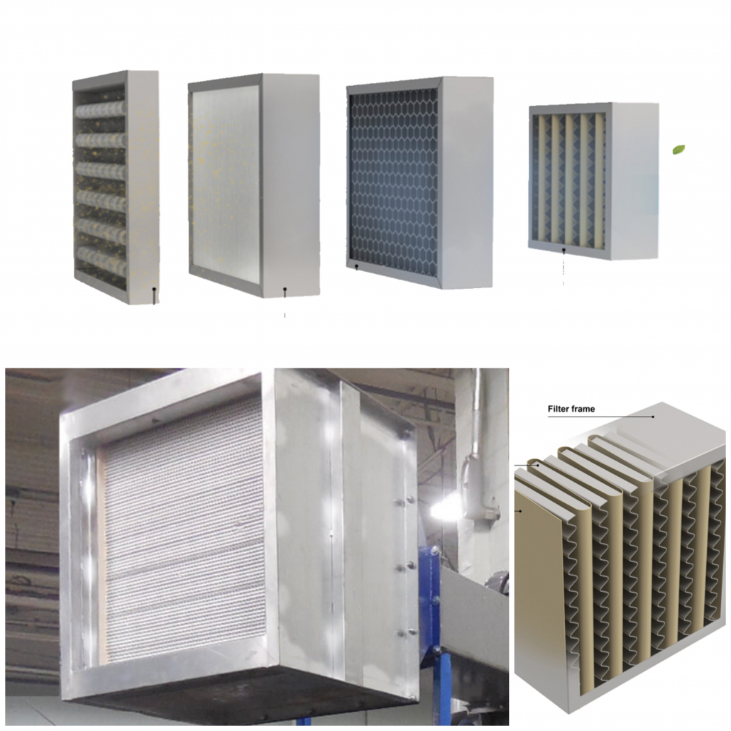
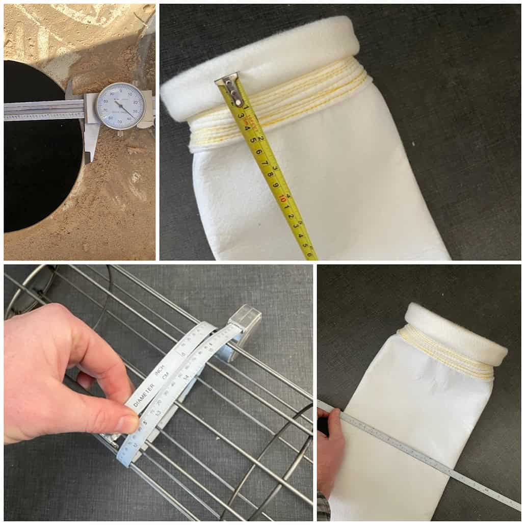
What is Dust Collector Air to Cloth Ratio? – The ratio of gas volume (ACFM) to total cloth area (sq. ft.) of the baghouse. First calculate the total cloth area of your collector by calculating the total filter area of each filter (bag diameter x 3.14 x length ÷ 144 [for number of inches in a square foot] = filter cloth area) and then multiply that figure by the total number of bags in the collector. Take the CFM of the system and divide it by the total filter cloth area to get your air to cloth ratio.
Why Important? – For the baghouse to capture the dust from the airstream the unit must have a sufficient number of filters. As you push more air through the same amount of filter material the collection efficiency goes down. Maintaining an adequate air to cloth ratio enables the baghouse to operate at peak efficiencies, collecting more than 99.9% all dust particles that pass through it. For most applications, anything less than near peak efficiency will result in excessive emissions, violating pollution regulations and creating hazardous environment for workers and neighbors.
Putting All 4 Variables Together and Designing Your System
Now that we have discussed the 4 key design considerations, we will now see how to design a baghouse dust collection system so as to maintain all 4 of these parameters within acceptable ranges to ensure proper operation. Our next section is titled: Design Process for Your Baghouse Dust Collection System
Next Section – Part 3 – Design Process for Your Baghouse Dust Collection System